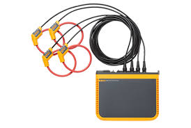
The Fluke 1742, 1746 and 1748 Three-Phase Power Quality Loggers give you fast, easy access to the data you need to make critical power quality and energy decisions in real-time. With the included Energy Analyze Plus software package you can easily create detailed reports.
Get the Fluke Guide to Choosing Power Quality Tools
The Fluke 1748 logs over 500 different parameters for each averaging period. This allows you to analyze power quality in detail and to correlate intermittent events with detailed waveform data, helping to identify the root cause of disturbances. For basic power quality logging, the Fluke 1746 captures all relevant power parameters for performing energy saving studies and electrical network planning with a full upgrade option to 1748 available. For simple load and energy studies the Fluke 1742 offers optimal performance in a rugged package and can be upgraded to 1746, or complete 1748, functionality.
Compact and rugged, the Fluke 1740 Series Three-Phase Power Quality Loggers are designed specifically for technicians and engineers who need the flexibility to troubleshoot, quantify energy usage and analyze power distribution systems. Fully compliant with international power quality standards such as IEC 61000-4-30 Class A and capable of simultaneously logging up to 500 parameters while also capturing events, the Fluke 1740 Series helps uncover intermittent and hard-to-find power quality issues more easily than ever. Energy Analyze Plus software quickly assesses the quality of power at the service entrance, substation, or at the load, according to national and international standards including EN 50160 and IEEE 519.
An optimized user interface, flexible current probes, and an intelligent measurement verification function that allows you to digitally verify and correct connections makes setup easier than ever and reduces measurement uncertainty. Minimize your time in potentially hazardous environments and reduce the hassle of suiting up in PPE by using a wireless connection (Wi-Fi) to view data directly in the field.
Capturing logged data is just one part of the task. Once you have the data, you need to create useful information and reports that can be easily shared and understood by your organization or customers. Fluke Energy Analyze Plus software makes that task as simple as possible. With powerful analysis tools and the ability to create customized reports in minutes you’ll be able to communicate your findings and quickly solve problems so you can optimize system reliability and savings. A range of built-in report templates for industry standards such as EN 50160, IEEE 519 and GOST enable one-click reporting so you can create high quality reports at the touch of a button. Reports can be modified as standards evolve, or new versions become available.
| Features | 1742 | 1746 | 1748 |
| Functions | |||
| Voltage, current, power, power factor, frequency | • | • | • |
| Energy forward/reverse | • | • | • |
| Peak Demand | • | • | • |
| THD | • | • | • |
| Flicker | • | • | • |
| Voltage and current harmonics (to 50th)1 | • | • | |
| Unbalance1 | • | • | |
| Rapid voltage change events1 | • | • | |
| Interharmonics (to 50th)1 | • | • | |
| Dips, swells, interruption and transient events tables1 | • | • | |
| Inrush current1 | • | • | |
| Transients (low frequency) / Waveform deviation events2 | • | ||
| Recording | |||
| Trend | • | • | • |
| Waveform snapshots2 | • | ||
| RMS profile2 | • | ||
| Communication | |||
| Ethernet | • | • | • |
| USB (mini B) | • | • | • |
| Wi-Fi download Instrument to device | • | • | • |
| Wi-Fi download via Wi-Fi hub (free with registration) | Opt. | Opt. | Opt. |
| Included accessories | |||
| Flexible current probe | not /B version | not /B version | not /B version |
| USB stick | • | • | • |
| USB cable | • | • | • |
| 3PHVL-17XX cable assembly | • | • | • |
| FLUKE-17XX-TL 0.18M test lead set | • | • | • |
| FLUKE-17XX-TL 2M test lead set | • | • | • |
| Alligator clips | 4 | 4 | 4 |
| 173x/174x Soft Case | • | • | • |
| Cable marker kit | • | • | • |
| MP1-3R/1B-Magnet Probe 1 set (3 red, 1 black) | Opt. | 1 | 1 |
| 174x-Hanger Kit | Opt. | Opt. | • |
| Specifications | |||||
| Accuracy | |||||
| Parameter | Range | Maximum Resolution | Intrinsic Accuracy at Reference Conditions (% of Reading +% of Range) | ||
| Voltage | 1000 V | 0.1 V | ±0.1 % of nominal voltage 1, 2 | ||
| Current: Direct input | i17xx-flex 1500IP 24 1500 A | 150 A | 0.01 A (min. 1.5A)3 | ±(1% + 0.02%) | |
| 1500 A | 0.1 A | ||||
| i17xx-flex 3000IP 24 3000 A | 300 A | 0.01 A (min. 3.0 A)3 | ±(1% + 0.03%) | ||
| 3000 A | 0.1 A | ||||
| i17xx-flex 6000IP 36 6000 A | 600 A | 0.01 A (min. 6.0 A)3 | ±(1.5% + 0.03%) | ||
| 6000 A | 0.1 A | ||||
| i40s-EL clamp | 4 A | 1 mA | ±(0.7% + 0.02%) | ||
| 40 A | 10 mA | ||||
| Frequency | 42.5 Hz to 69 Hz | 0.01 Hz | ±(0.1%)2 | ||
| Auxiliary input | ±10 V dc | 0.1 mV | ±(0.2% + 0.02%) | ||
| Voltage min/max | 1000 V | 0.1 V | ±0.2 % of nominal input voltage1 | ||
| Current min/max | Defined by accessory | Defined by accessory | ±(5% + 0.2%) | ||
| THD on voltage | 1000% | 0.10% | ± 2.5% | ||
| THD on current | 1000% | 0.10% | ± 2.5% | ||
| Voltage harmonics 2nd to 50th | 1000 V | 0.1 V | ≥ 1 V: ±5% of reading | ||
| < 1 V: ±0.05V | |||||
| Current harmonics 2nd to 50th | Defined by accessory | Defined by accessory | ≥ 3% of current range: ±5% of reading | ||
| < 3% of current range: ±0.15% of range | |||||
| Flicker PLT, PST | 0 to 20 | 0.01 | 5% | ||
| Current probe accuracy | |||||
| Parameter | Influence quantity | iFlex1500IP-24 | iFlex3000IP-24 | iFlex6000IP-36 | i40S-EL |
| 150 A / 1500 A | 300 A / 3000 A | 600 A / 6000 A | 4 A / 40 A | ||
| Active Power P | PF ≥ 0.99 | 1.2% + 0.005% | 1.2% + 0.0075% | 1.7% + 0.0075% | 1.2% + 0.005% |
| Active Energy Ea | |||||
| Apparent power S | 0 ≤ PF ≤ 1 | 1.2% + 0.005% | 1.2% + 0.0075% | 1.7% + 0.0075% | 1.2% + 0.005% |
| Apparent Energy Eap | |||||
| Reactive power Q | 0 ≤ PF ≤ 1 | 2.5% of measured apparent power | |||
| Reactive Energy Er | |||||
| Power Factor PF | - | ±0.025 | |||
| Displacement Power | |||||
| Factor DPF/cosΦ | |||||
| Additional uncertainty in% of range | VP-N>250 V | 0.015% | 0.023% | 0.023% | 0.015% |
| 1 In the range of 100 V … 500 V; also known as Udin 2 0 °C … 45 °C: Intrinsic accuracy x 2, outside of 0 °C … 45 °C: Intrinsic accuracy x 3 3 Consult operators manual for details Reference conditions: Environmental: 23 °C ± 5 °C, instrument operating for at least 30 minutes, no external electrical/magnetic field, RH <65 % Input conditions: Cosφ/PF=1, Sinusoidal signal f=50 Hz/60 Hz, power supply 120 V/230 V ±10 %. Current and power specifications: Input voltage 1 ph: 120 V/230 V or 3 ph wye/delta: 230 V/400 V Input current: I > 10 % of I range Primary conductor of clamps or Rogowski coil in center position Temperature coefficient: Add 0.1 x specified accuracy for each degree C above 28 °C or below 18 °C | |||||